
The gyrator
An ideal gyrator is a two port network whose input (respectively output) voltage (respectively output) is directly proportional to the output (respectively input) current. The ratio
 is usually called the "gyration resistance". In the case of this lecture, we will use the "coupling factor" (for reasons that will become apparent in the following lectures, see section 3.2).
In the case of an asymmetrical respresentation, a gyrator is illustrated by:
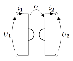
The relations between current and voltage are written:


where
 and
and
 represent the number of primary (subscript
 on schematic) and secondary (subscript
 on schematic) windings.
Attention : Caution
The electrical impedance
 at the input of the gyrator depends on the admittance at the output
 :
:
 .
.


